For whatever reason I was feeling incredibly tired today. Just dead, beat, tired. No idea why. I had a lot of late work on Thursday and maybe it was just time catching up with me, but only had a few hours to spend in the garage today interspersed with naps. Just so … freaking… tired.
First up, at some point in the day, was to attach the brake connection to the parking brake. It went into the top electrical connection (there are two) and then routed the wire around the back of the handle and zip tied as shown below.

Next up was to remove the boot floor. I’d read on one of the other blogs that the owner had put some polyurethane on it. Since its wood, and exposed to the elements, figured it was probably a good idea to do so; held in with some self tapping wood screws, easy enough. I kind of giggled at that; a car with wood in it! Ha! Every time I think of wood in a car I think of Morgans. View of the diff with the boot floor out. Note, this will make filling the diff incredibly easy and is my intent to fill through there (another build blog tip).

Once the floor was out, I moved onto the large L water hose which runs to the upper radiator inlet. Prior I’d noticed it was a little long and thus rubbing against the chassis so needed to cut off a bit to route it better. Easily done, but may have cut off a tad too much as now its rubbing against the air intake (not shown in picture). I’ll leave it as is for now and if it becomes a problem later on replace it.

Once I was ok with the upper radiator hose I moved onto the throttle body and air intake. Finding the parts was easily enough based on Dave’s build blog, however, my throttle body mounting point isn’t drilled out. WTF – how does that make it out of QA? So I’m unsure how this is supposed to be drilled or secured. On the UK builds I noticed they mount their throttle body retaining clip on the outside of the throttle body bracket, but my part is machined to be inside the throttle body clip. Another frustrating setback and delay from Caterham while I wait for an answer. Of course nothing is in the manual – I’ve actually found myself referring to it less and less these past few days because the build blogs are either a) more current or b) the manual literally doesn’t mention anything of the sort.
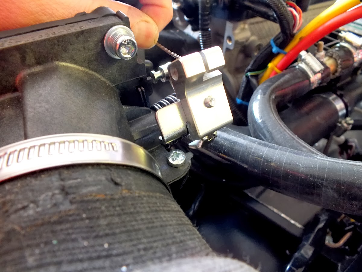


With that the air intake on hold, I moved onto the radiator. After reading another build blog, I discovered the correct way to attach everything is the plastic clips go onto the fan, those in turn attach to the fan brackets and then get bolted together with the bolts, washers, and nyloc nuts as shown below.

Once the bracket is assembled, then it slides onto the rubber mounts for the radiator, then the radiator over that. The flat part of the fan obviously attaches to the radiator side and the curved part extends into the engine bay. The wiring harness should be hanging down near the cruciform, just below the water bottle. Pic of the radiator on temporarily – I intend to paint it all black before final assembly but was out of flat black paint (now since acquired). The oil cooler goes onto the lower mount points and aligns as show below. I need to drill out the 8mm hole for the upper oil cooler bolts into the radiator mounting brackets, but will do that once I get it all painted and prepped. The top radiator hose also needs to be trimmed but will do that during final fitting (the lower hose actually looks like its the right size).

Once thing I noticed when doing the test fitting is the radiator has an odd torque to it. You can see the difference in the top and bottom of the oil cooler bracket in the pic below. I’m not overly worried about it as once things are bolted in it will be pulled taught but something worth mentioning.

The other thing I noticed is the rubber bobbins for the radiator were hitting the paintwork. Will need to either file down the integrated bobbin bolt or to add a washer or two.

Next up was to fiddle with the heater cable. I was having a hard time getting a flat headed screw driver on the little screw holding the retaining bracket but since it had a 6-sided hex on it as well I grabbed a box end wrench and got it into place. Full routing of the heater cable on a US/LHD 7 for reference.

Once done with that I went back to the oil cooler and started playing around with the oil cooler lines. Of course at this point I’ve drifted away from the manual, the Duratec Roadsport 175 doesn’t have oil coolers but the R400 does, so I’m in a weird limbo state as far as the manual goes. I gave it a read, then proceeded with my own intuition having got the basics down from the Caterham manual. Having the Elise and Exige also helps – they both have similar oil cooler setups so went with a similar setup to their shop manual. It’s mildly amusing I’m using current Lotus manuals to determine how to assemble a Caterham, which is technically a Lotus from 1968 (Series 3). At the end of trying different routes, I think I’ve decided to route the oil lines across the bottom of the chassis as show below (only the shorter hose run so far in the pic).

It was no getting late and I still had that tired thing going on, but did manage to open the carpets up just to test out fitment. Good news is they all seem to fit really well – no extra trimming needed – and will proceed to start getting those into place next week.

And the carpet in the boot also fits.

After that, it was time to head upstairs and call it a night.
Daniel